
12/8/20 The third article of the blog series about using open-source tools on Unipi programmable logic controllers will demonstrate communication with external devices using the Modbus protocol.
Introduction
Welcome to the third part of the series about using open-source software on Unipi PLCs. The previous article demonstrated usage of integrated inputs/outputs of an Unipi Neuron controller, measurement of temperature using a 1-Wire sensor and creation of a simple Node-RED sample project of a thermostat with hysteresis.
However, in some projects, you may need more inputs/outputs, additional types of I/Os or other peripherals than the controller in question features. In such cases, one of the possible solutions is to use an extension module featuring the needed peripherals. These modules can use various methods to communicate with the PLC. RS485 serial interface and Ethernet are the most common communication methods and as are also the topic of this article.
Two Unipi products are used in the text below - RW-THC indoor air quality sensor and Unipi Extension xG18 extension module, with both utilising the Modbus protocol. Given the widespread use of Modbus, you can also use it to integrate a wide range of other devices from different vendors.
Modbus
This protocol has been in use since 1979 and is among the most frequently used protocols in the sphere of monitoring and regulation. Its main advantages are its simplicity and low system requirements. A more detailed look on Modbus is beyond this article’s scope - on this link, you can find all relevant info.
As to its characteristics, Modbus is a Client-Server protocol where the client is a master device (a PLC in our case) while the server is represented by an extension module, smart sensor or other external devices. The protocol exists in RTU, ASCII and TCP variants differing in context format or coding of the individual values. The following example focuses on RTU and TCP as the most frequently used variants, which require a set of specific parameters to be configured on both sides of the communication:
- Address/device identification - a unique number used to identify the Modbus server,
- Parity and bitrate or stop bit number (does not apply for Ethernet/TCP connection) - all devices within a single segment usually share the same RS485 parameters,
- IP address and port (only for TCP) - an IP address is assigned statically or dynamically. Port 502 is used commonly for TCP but is also freely configurable.
Modbus devices usually provide multiple values taking the form of measured data, configuration parameters etc. These values are represented within registers arranged into a register map, whose description should be an integral part of any Modbus device documentation.
RW-THC indoor air quality sensor
The first device we will connect to a Unipi controller is the RW-THC indoor air quality sensor.
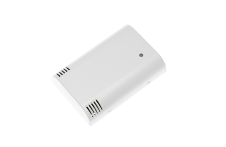
The sensor is designed for installation in building interiors and can be used to measure the following parameters:
- Temperature
- Humidity
- CO2 concentration
- Volatile organic compound concentration (VOC)
- Barometric pressure
- Ambient light intensity
The sensor uses two interfaces to communicate with the control system - RS485 (Modbus RTU) and wireless Wi-Fi interface (Modbus TCP). The second interface will be used in the example project below.
Unipi Extension xG18
The xG18 module allows the connection of up to eight Unipi 1-Wire DS18B20 temperature sensors communicating via Modbus RTU.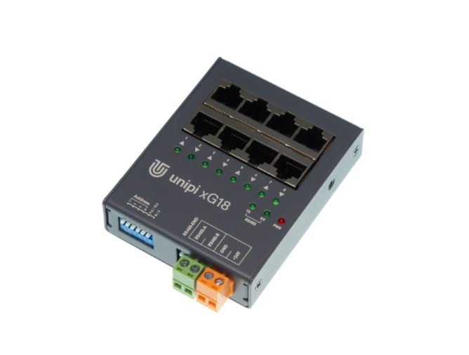
Aside from serial communication parameters (address, bitrate, parity), the module also allows you to configure the reading period independently for each 1-Wire channel.
Communication test
Before integrating external devices to an IDE, we recommend testing the communication first to ensure all physical connections are available and communication parameters are correctly configured. A quick and easy method of doing so is the mbpoll program included in the OS Debian standard repository.
-----------------------------

pi@M203-sn55:~ $ sudo apt install mbpoll

-----------------------------
This tool serves as a client for both Modbus RTU and TCP.
Let’s start by testing the communication with xG18, which is connected to the Unipi Neuron M203 controller via its single RS485 interface available at /dev/extcomm/0/0. An overview of serial interfaces is available HERE for the Axon line and HERE for the Neuron line. If the connected device is the only device connected to the bus or is connected as of last, you need to attach the 120Ω terminating resistor by using the corresponding DIP switch.
The xG18 module’s parameters can be configured in two ways:
- Software configuration: parameters match contents of the corresponding registers,
- Hardware configuration: positions of DIP switches determine parameters.
For this article, we will go for the second option suitable in a situation when you don’t know the contents of configuration registers. If all DIP switches are set to ON, the module has address 15, 9600 baud bit rate and communicates with no parity. A successful mbpoll test using these settings can then look like the following:
pi@M203-sn55:~ $ mbpoll -1 -a 15 -b 9600 -t 3 -r 1 -c 9 -P none /dev/extcomm/0/0 -0

…

-- Polling slave 15...

[1]:    3037

[2]:    2906

[3]:    2881

[4]:    2875

[5]:    2856

[6]:    2868

[7]:    2943

[8]:    3012

[9]:    255
By looking at the mbpoll-u output and the xG18’s Modbus register map included in the product’s documentation, we can see all (i.e. 8) 1-Wire temperature sensors are connected. Register 9’s bitmask then tells us all sensor values are valid. However, to obtain temperature values in degrees Celsius, we need to divide the content of all integer registers by 100.
For devices connected via Modbus TCP, the process is very similar. In the case of the RW-THC sensor, you need to know its IP address and TCP port. The IP address can be detected by several methods, one of which is the Online discovery service function included in the sensor itself. The feature is described in the sensor’s user manual.
Let’s assume we have detected the IP address and the port remained unchanged (i.e. 502). Mbpoll test then looks like this:
pi@M203-sn55:~ $ mbpoll 10.251.17.15 -a 1 -B -t 3:float -r 0 -01

…

-- Polling slave 1...

[0]:    28.0581
Note: The input 32-bit register at address 0 contains temperature value expressed in 32bit big-endian float data type. Use the -h switch to display documentation for mbpoll-u switches.
Module integration into Node-RED
Let’s assume the communication between the PLC and both devices is tested and functional. The most direct method of inserting the values into Node-RED is via the Modbus protocol node. This node needs to be installed from a repository using the following guide: in the main menu, click on Manage Palette -> Palette -> Install, enter “Modbus” into the search engine and install the node-red-contrib-modbus package.
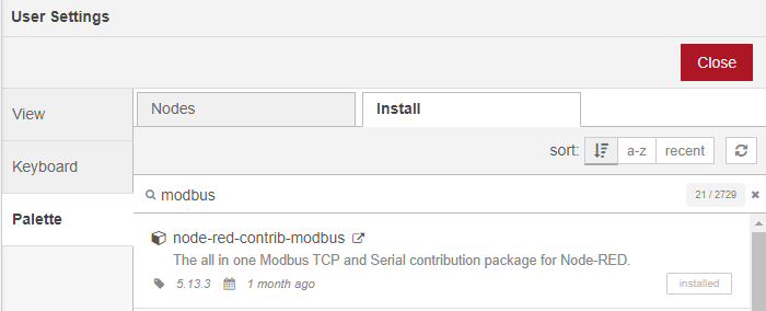
Upon installation, a new category will display in the list of all available nodes related to Modbus. For this article, Modbus Read and Modbus Response will be sufficient - the former represents a Modbus server while the latter displays raw data of read registers.
The first step is to create two standalone Modbus servers - one for RS485/RTU and one for TCP. All parameters remain the same as in the mbpoll tool test.
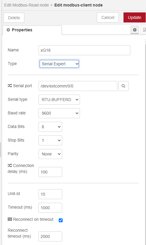
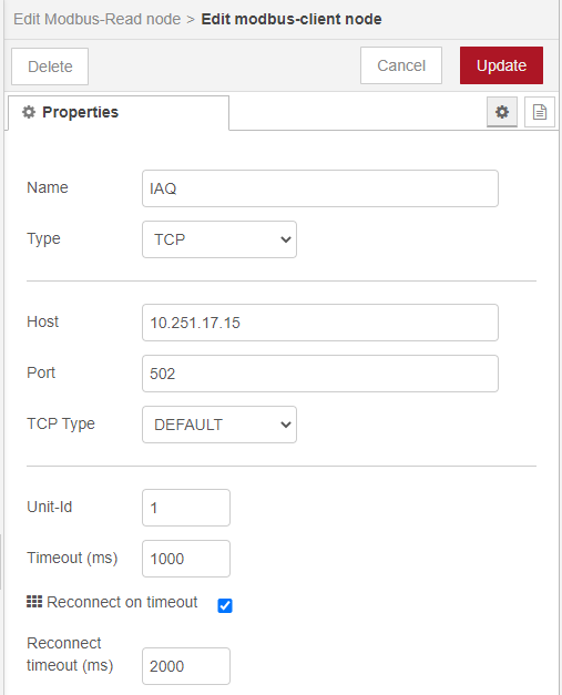
The next step is to assign the Modbus server to specific devices. For simplification, only the current temperature value will be read from both devices. The process stays the same for other parameters/registers. On RW-THC the Modbus-READ block parameters will be as following (reading from 2 two-byte input registers at address 0):
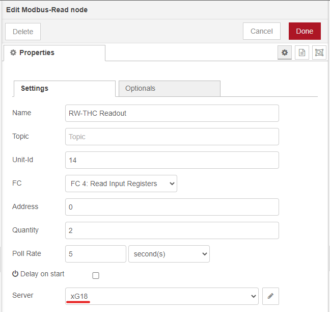
However, bear in mind the raw values read from the devices cannot always be used directly (e.g. for their visualisation). In such a case, you need to recalculate the values, with xG18 and RW-THC not being an exception. For the xG18 module, you need to divide the read integer value by 100 to acquire a decimal number in degrees Celsius. With RW-THC, several logic operations need to be performed with two 16-bit registers to receive a big-endian floating-point number. The content of conversion blocks can then look like this:
// Convert float32

var buffer = new ArrayBuffer(4);

var view = new DataView(buffer);


view.setInt16(0, msg.payload[0], false);

view.setInt16(2, msg.payload[1], false);


var res = view.getFloat32(0, false);


var newMsg = { payload: res };

return newMsg;

----------------------------------------------


// Divide by 100

var newMsg = { payload: msg.payload[0]/100 };

return newMsg;
The resulting flow for reading values from both Modbus devices and their recalculation can look similar to the picture below:

Debug and Modbus Response blocks serve only for debugging and display only data before and after the conversion.
You can download the flow in JSON format on this link.
Conclusion
In this article, we connected the RW-THC indoor air quality sensor and Extension xG18 module to the Unipi Neuron M203 controller. Both devices utilise the Modbus protocol for communication, but differ in their communication interface - while the xG18 features RS485 interface, the RW-THC sensor uses TCP/IP. You can save some time by testing the communication using the simple mbpoll tool before integration of devices into Node-RED. We also demonstrated a simple conversion of data types in Node-RED, as the obtained values are not always in a suitable format.


